Having seen the basic principle of Monopulse Tracking we now concentrate on the special components and circuits used for the derivation of actual tracking errors.
Antenna
and Feed:
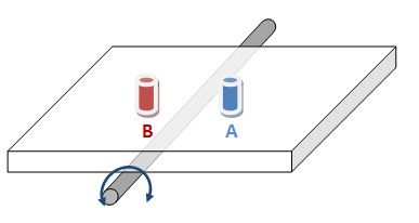
A voltage proportional to the angular
difference
between Antenna axis and Target can be derived
by vectorial
subtraction ( A - B ).
How do we derive the error signals from these elements? We use what is called a Monopulse comparator. In one of the simplest forms transmission lines of l/4 and 3*l/4 are used in a ring fashions as shown in next figure.
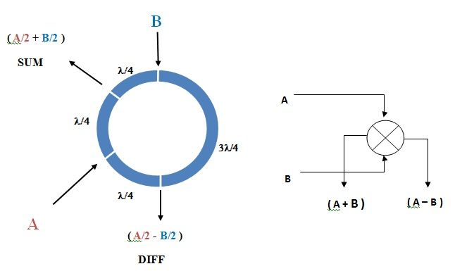
The working principle is straight forward:
A gets divided equally into
two paths each with a strength A/2 ;
One travelling to SUM port and
another A/2 travelling to DIFF ( = Difference ) port .
One travelling to SUM port and
another A/2 travelling to DIFF ( = Difference ) port .
A similar split
happens to B input.
At SUM
port both A/2 and B/2 travel same path length and so they
get added vectorially to ( A/2 + B/2 ).
At the DIFF port A/2 components travels l/4 while the B/2
component travels 3l/4,
that is it
travels l/4 + 2l/4 ( = l/2
) and so the output becomes A/2
plus ( B/2 with a phase reversal
), so effectively you get ( A/2 - B/2 ) at the output.
Althogh really the values are ( A/2
+ B/2 ) and ( A/2 - B/2 ) they are denoted as ( A + B ) and ( A
- B ) which though theoretically wrong is the
convention universally used for simplicity as we are not doing a critical mathematical evaluation.
So we will use SUM = S = ( A + B ) and DIFF = D = ( A
- B ) as the convention here onwards.
Two Axis Monopulse Feed:
We have seen that two elements are required
to measure the angular difference for one axis.
Antennae
generally have two axes for Horizon to Horizon coverage hemisphere ( e.g. AZ/EL or X/Y or Ha/Dec etc. ).
It follows
that there should be 4 elements to track in 2 axes.
In the example we assume that there are two
axes X and Y supporting the antenna and the four elements can be placed in two
fashions ..
a.
Cross or On axis elements arrangement where the elements are mounted on axes and
the
error about X axis would be given by the quantity ( A – B )
and Y Error would be ( C – D ).
and Y Error would be ( C – D ).
While another arrangement would be
b.
Diagonal arrangement where the
elements are placed in a 2 on each side of axes equally spaced from each axis
and In this case X arror would be ( ( A +
B ) – ( C + D ) )
and Y Error would be ( ( A + D ) – ( B + C ) ) .
and Y Error would be ( ( A + D ) – ( B + C ) ) .
Two arrangements are graphically shown in the figure below.
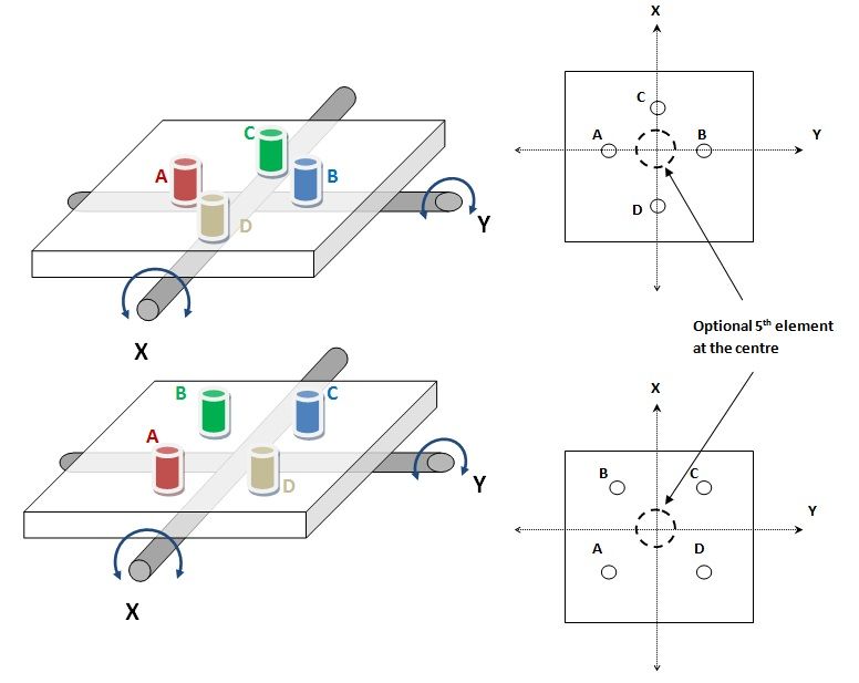
Notice that in second case the error is a
difference of two additions so it is
less prone to errors and is more sensitive.
That is the reason why it is commonly used.
How do we derive the error signals from
four elements? We use a set of Monopulse comparators.
In 1st
case of Cross arrangement of elements we
use a set of 3 hybrids as shown hree.
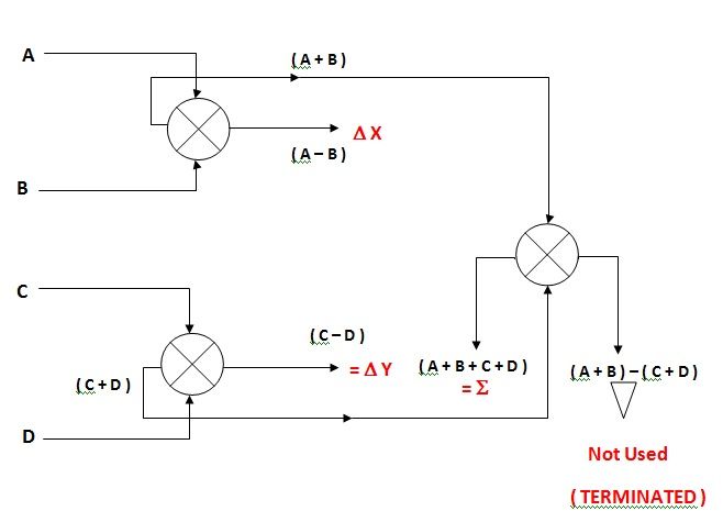
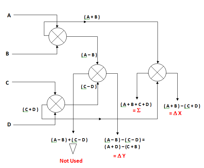
Four hybrids are required to derive
tracking errors if we use the 2nd
i.e. Diagonal arrangement of elements as shown below.
Although 4 elements are sufficient to
derive errors in two axes, several
other more complex arrangements are used
in sophisticated applications.
One of the most common is to use a 5th
element at the centre of 4 elements A
thru D as DATA pickoff element. This
is useful in Parabolic reflector antennas since the error elements are always away
from the prime focus of main reflector so receive less signal than what is
available at the prime focus. More on
this subject in a later post.
We have shown here the most commonly used
arrangements. The elements themselves could be Dipoles/Cross-Dipoles/Helices or
Horns. There are several complex variations in use .
A few designs also use a single
Horn feed fabricated such that Error
outputs are derived at the output by multimode horn excitations .
There are also multielement feeds
wherein upto 12 elements are used to derive the Errors for
better sensitivity and flatter phase response over wide frequency range of
operation.
We will not go into more complex
configurations but just mention here that in reflector antennas ( e.g Parabolic
or Cassegrain ) generally a fifth element is added in the centre. This is not
for tracking but is used as an independent DATA receiving element.
Next post covers the overall tracking system including error computing processor.
Back to Main Index
No comments:
Post a Comment